|
Always wear safety glasses when operating machine tools. |
Download PDF 8815 Pneumatic Bar Feeder Activation Cylinder Instructions
|
Back to Bar Feeder
")
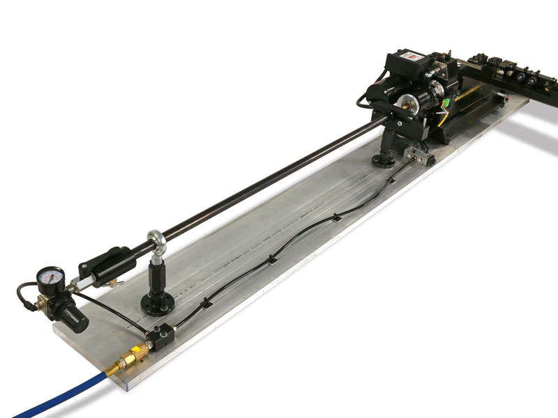
The Pneumatic Air Cylinder mounted to a CNC Chucker Lathe (machine not included)
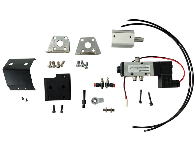
Pneumatic Bar Feeder Activation Cylinder Assembly
We’ve separated the Bar Feeder into two components to better support customers who want to build their own custom bar feeder system.
Beyond its use in a bar feeder setup, this assembly can also function as a programmable collet control for opening and closing the collet. You can use M10 and M11 G-code commands to close and open the chuck, respectively.
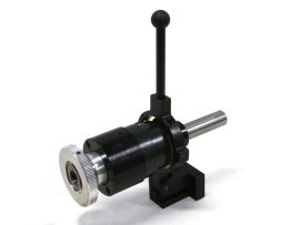
The Pneumatic Bar Feeder Activation Cylinder Assembly works with our machine and 3C lever collet closer to pneumatically open and close the collet. Click the “Instructions” tab above to download setup documentation.
NOTE: This system is designed for use with the MASSO Touch controller featuring the G3 board. The older G2 board is not compatible with the required MASSO relay module. If you are using a control system other than the MASSO Touch, please consult your controller manufacturer for wiring diagrams and compatibility. Most modern CNC controllers are designed to send relay signals to control external devices.
-


- Air supply must be 80 PSI, minimum.
- Air pressure for the air cylinder (P/N 88040) is 70 PSI, maximum. However, we recommend 40 PSI. This is controlled by the air supply.
- Air pressure for the bar feeder is 20-30 PSI. This is controlled by the bar feeder air regulator (P/N 88054). CAUTION: DO NOT EXCEED 30 PSI!
- Lubrication for the bar feeder tube and the lever collet closer. We recommend a light machine oil such as “3-in-1 Oil,” or sewing machine oil.
- Base dimensions: Our base (P/N 88323) is 6′ x 8″ x 3/4″. If you are mounting the bar feeder on a different work surface, the surface must be at least 6′ long.
Introducing the Sherline Pneumatic Bar Feeder
Running a Part Program with the Pneumatic Bar Feeder
| Part No. | Description | Quantity |
|---|---|---|
| 12060 | #8 Washer | 2 |
| 40670 | 10-32 x 1/2″ SHCS | 2 |
| 45014 | 5-40 x 3/8″ Button Head socket cap screw | 2 |
| 88040 | Air cylinder | 1 |
| 88041 | Air cylinder foot brackets (R & F) w/4 SS SHCS | 1 |
| 88042 | Air directional control valve | 1 |
| 88043 | 5/32″ Connector fitting | 2 |
| 88044 | 1/4″ Connector fitting | 1 |
| 88045 | Heim joint | 1 |
| 88046 | 1/4-28 SS threaded rod | 1 |
| 88047 | 1/4-28 Jam nut | 2 |
| 88049 | 8-32 x 1-1/4″ SHCS | 2 |
| 88050 | Flow control valve | 2 |
| 88052 | 5/32″ (4 mm) air line (6′ length) | 2 |
| 88056 | Air cylinder mounting plate | 1 |
| 88058 | Air cylinder cover | 1 |
| 88060 | 1/4-20 Phillips head screw | 3 |
| 88279 | LCC Stud | 1 |
Related products
Pneumatic Bar Feeder
Streamline your machining process with the Sherline Pneumatic Bar Feeder. Designed for use with our CNC lathes, this feeder ensures consistent material delivery, improving efficiency and productivity in automated machining tasks.