|
Always wear safety glasses when operating machine tools. |
Download PDF Assembly and Instruction Guide
| Download PDF 10″ Mill Base Dimensions
|
Download PDF 5000/5400 Mill Column Base Dimensions
|
Back to CNC-Ready Mills

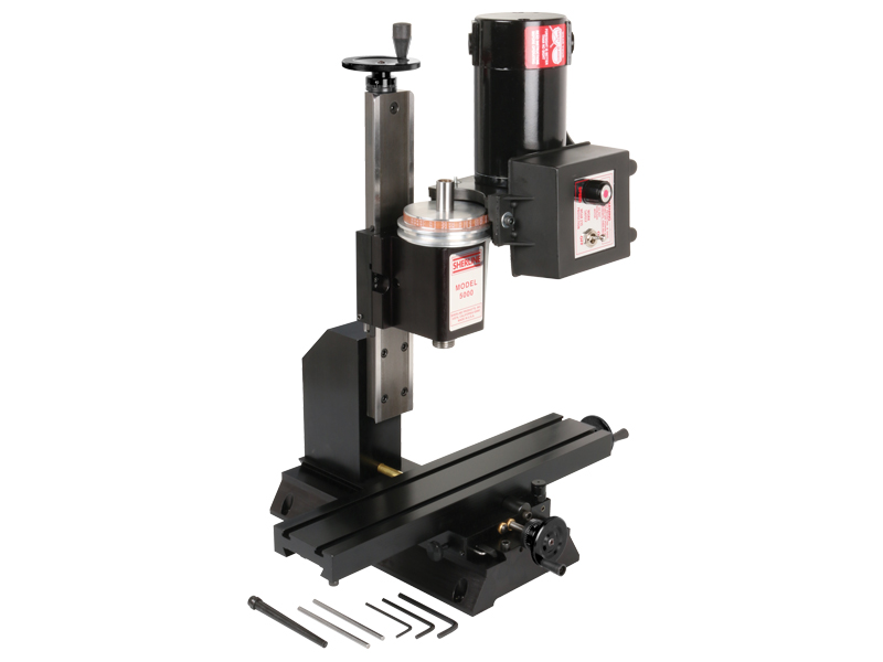
12" CNC-Ready Mill

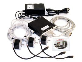
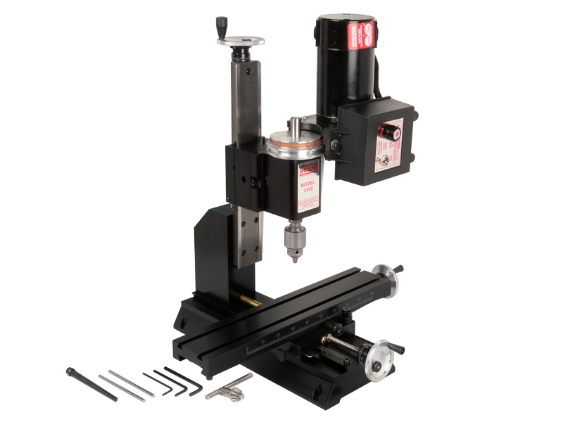
12" CNC-Ready Mill with optional accessory package
12″ CNC-Ready Mill
Our CNC-ready tabletop mill is ideal for customers seeking a compact CNC milling solution for producing small, precision parts. Made in the USA and backed by exceptional customer service, this mill offers full-size machine accuracy in a desktop footprint. Despite its size, it’s capable of cutting wood, plastic, aluminum, and even steel with impressive rigidity and precision.
CNC-ready mills come with factory-installed stepper motor mounts in place of handwheels and are ready for you to add your own stepper motors and CNC controls. Please note: these are not turn-key systems and cannot be operated until motors and controls are installed. CNC-ready machines do not include stepper motors, a computer, or CNC software.
Sherline recommends dual-shaft stepper motors so manual control is still possible using the included handwheels, which mount to the rear shaft once the motors are installed. Sherline also offers high-quality stepper motors and CNC components to complete your system.
Additionally, you can explore various aftermarket suppliers for compatible motors, drivers, and software. Visit our CNC Dealers page for a list of suppliers and links to their websites.
Note on Ordering a Metric Mill – Most Sherline cutting tool, such as center drills, are offered in fractional sizes. If you opt for a metric machine with metric collets or holders, you’ll need to order compatible fractional-size holders to use these tools effectively.
Standard Equipment for the 12″ Deluxe Tabletop Mill
- A powerful 90V DC motor with electronic speed controller
- 12″ base with laser-engraved scales
- Brass leadscrew cover that keeps chips off the rear of the Y-axis leadscrew
- 2.75″ (70 mm) x 13.0″ (330 mm) table with laser-engraved scales and two T-slots
- 1.235″ headstock spacer block
- Resettable, zero-adjustable handwheels that can be mounted to the end of the stepper motors to maintain manual control when needed:
- (2) 2″ (51 mm) handwheels on X- and Y-axes
- (1) 2-1/2″ (63 mm) handwheel on Z-axis
- All with laser-engraved aluminum collars
- NOTE: CNC-ready machines cannot be operated manually unless double-shaft stepper motors are installed.
- ¼” Drill Chuck w/ key, #1 Morse arbor with drawbolt
- Pulleys, drive belt, three hexagonal keys, spindle bars, gib removal tool, eight-foot three-wire power cord, and instruction manual
- Oil reservoirs on the X/Y axes and the Z axis help keep critical parts lubricated. These were initially developed for CNC machines that run constantly for hours on end but can benefit manual machines as well
-


| Max clearance (table to spindle) | 8.00″ (203 mm) |
|---|---|
| Throat (no spacer) | Optional |
| Throat (w/ headstock spacer) | Adjustable |
| Travel, “X” Axis | 8.65″ (220 mm) |
| Travel, “Y” Axis | 5.00″ (127 mm) |
| Travel, “Z” Axis | 6.25″ (159 mm) |
| Hole through spindle | .405″ (10 mm) |
| Spindle nose thread | 3/4″-16 T.P.I. |
| Spindle nose taper | #1 Morse |
| Spindle runout of Morse taper | .0005″ or less |
| Handwheel graduations | .001″ (.01 mm) |
| Electronically controlled spindle speed range | 70 to 2800 RPM |
| Width Overall* | 15.00″ (381 mm) |
| Depth Overall* | Base footprint: 13.75″ (379 mm); With fully extended brass leadscrew cover: 16.75″ (425.5 mm) |
| Height Overall (Max.)* | 20.75″ (527 mm) |
| Table size | 2.75″ x 13.00″ (70 x 330 mm) |
| Hold-down provision | 2 T-Slots |
| Shipping Weight | 40 lb. (18.2 kg) | Movements in addition to X-, Y- and Z-axes | Headstock rotation (90° left/right) |
| Motor | 90 volt DC with electronic speed control that accepts any incoming current from 100VAC to 240 VAC, 50 Hz or 60 Hz. Click here for motor specifications |
| Spindle Speed Range | 70-2800 RPM continuously variable by electronic speed control |
*Overall dimensions include motor and speed control
Click on the link for the exploded view of the 5000 and 5400 Series CNC-Ready Mills to help identify replacement parts.
If you are still uncertain please call our customer service representatives for help with this item.
Click the P/Ns below to download a zipped version of the IGS 3D CAD file. You will need to extract the zip file before viewing the files.
5400 CNC-Ready 3D IGS model
You need an IGS viewer to open .igs files. CLICK HERE to download a FREE IGS viewer.
 |  |  |  | |
|---|---|---|---|---|
| 5000 (5100) | 5400 (5410) | 2000 (2010) | 5800 (5810) | |
| Max. clearance (table to spindle) | 8.00″ (203 mm) | 8.00″ (203 mm) | 9.00″ (229 mm) | 14.00″ (356 mm) |
| Throat (no spacer) | 2.25″ (50 mm) | 2.25″ (50 mm) | Adjustable | Adjustable |
| Throat (w/ headstock spacer) | Optional | 3.50″ (90 mm) | Adjustable | Adjustable |
| Travel: X-axis (with stop) | 8.65″ (220 mm) | 8.65″ (220 mm) | 8.65″ (220 mm) | 13.65″ (347 mm) |
| Travel: Y-axis | 3.00″ (76 mm) | 5.00″ (127 mm) | 7.00″ (178 mm) | 11.00″ (279 mm) |
| Travel: Z-axis | 6.25″ (159 mm) | 6.25″ (159 mm) | 5.38″ (137 mm) | 9.38″ (238 mm) |
| Hole through spindle | .405″ (10 mm) | .405″ (10 mm) | .405″ (10 mm) | .405″ (10 mm) |
| Spindle nose thread | 3/4-16 T.P.I. | 3/4-16 T.P.I. | 3/4-16 T.P.I. | 3/4-16 T.P.I. |
| Spindle nose taper | #1 Morse | #1 Morse | #1 Morse | #1 Morse |
| Spindle runout of Morse taper | .0005″ or less | .0005″ or less | .0005″ or less | .0005″ or less |
| Handwheel graduations | .001″ (.01 mm) | .001″ (.01 mm) | .001″ (.01 mm) | .001″ (.01 mm) |
| Handwheel Type | Standard Handwheels | Zero Adjustable Handwheels (With the exception of DRO machines which come with DRO handwheels) | Zero Adjustable Handwheels (With the exception of DRO machines which come with DRO handwheels) | Zero Adjustable Handwheels (With the exception of DRO machines which come with DRO handwheels) |
| Electronically controlled spindle speed range | 70 to 2800 RPM | 70 to 2800 RPM | 70 to 2800 RPM | 70 to 2800 RPM |
| Width overall | 14.75″ (375 mm | 15.00″ (381 mm) | 15.00″ (381 mm) | 20.00 (508 mm) |
| Depth overall | 11.75″ (298 mm) | 14.00″ (356 mm) | 22.25″ (565 mm) | 23.13″ (588 mm) |
| Height overall (Max.) | 20.75″ (527 mm) | 20.75″ (527 mm) | 23.38″ (568 mm) | 24.50″ (622 mm) |
| Table size | 2.75″ x 13.00″ (70 mm x 330 mm) | 2.75″ x 13.00″ (70 mm x 330 mm) | 2.75″ x 13.00″ (70 mm x 330 mm) | 2.75″ x 18.00″ (70 x 457 mm) |
| Hold-down provision | 2 T-slots | 2 T-slots | 2 T-slots | 3 T-slots |
| Shipping weight | 33 lb (15.0 kg) | 36 lb (16.3 kg) | 38 lb (17.2 kg) | 50 lb. (22.7 kg) |
| Movements in addition to X-, Y- and Z-axes | Headstock rotation (90° L/R) | Headstock rotation (90° L/R) | Headstock rotation (90° L/R) | Headstock rotation (90° L/R) |
| Column rotation | N/A | N/A | (90° L/R) | N/A |
| Column pivot | N/A | N/A | (90° Fwd/Bk) | (90° Fwd/Bk) |
| Column swing | N/A | N/A | (90°L/R) | (90°L/R) |
| Column travel | N/A | N/A | (In/Out) 5.5″ (140 mm) | (In/Out) 5.5″ (140 mm) |
| Motor Specs | ||||
| Input voltage | 100 to 240 VAC, 50 or 60 Hz | |||
| Output to motor | 90 VDC | |||
| Current draw | .5 to 15 amps depending on load | |||
| No-load output shaft speed | 6000 RPM (no pulley) | |||
| Click here for more detailed specs | ||||
| Spindle Specs | ||||
| Spindle End play (factory adjustment of preload) | .0002″ (.005 mm) or less, normal pulleys | |||
| Runout at nose | .0005″ (0.013 mm) or less | |||
| Bearings | Two 20 mm lifetime lubricated ball bearings with adjustable preload | |||
Related products