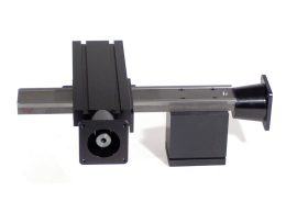
Product Description
- The slides are manufactured primarily from 6061-T6 aluminum and finished with a black anodizing. The slides that incorporate steel parts have ground dovetails.
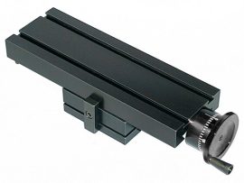
- The table is 8″ x 2.75″, and any table is available with either an inch or metric leadscrew.
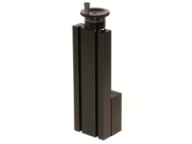
- The column is 11″ steel with ground dovetails with either an inch or metric leadscrew.
- Leadscrews are precision rolled from steel, and table screws are located under the table, out of the way of chips. Leadscrew backlash is adjustable.
- Dovetailed tables and saddles have adjustable gibs to eliminate play.
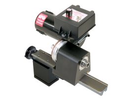
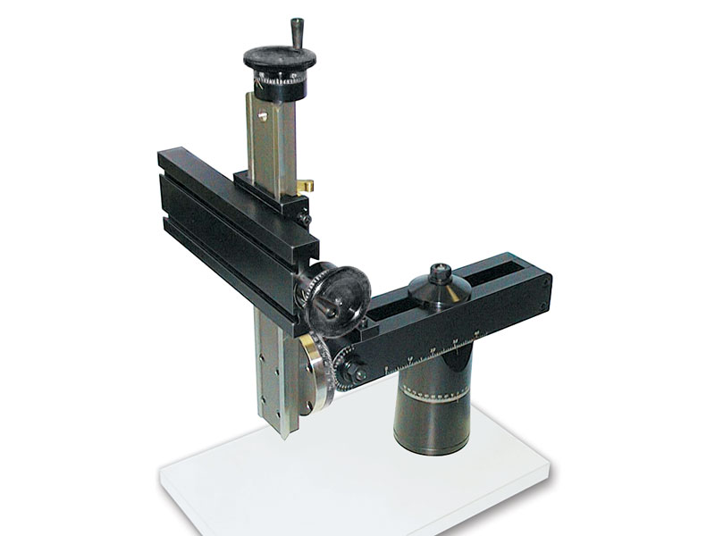
- Travel includes X- and Z-axis movements by handhweel, plus manual ram control for the column rotation, pivot, swing, and in/out travel.
- 2″ Industrial handwheels are graduated in .001″ increments on inch slides and in .01 mm increments on metric slides.
Mounting Provisions
FROM THE BOTTOM—Two 1/4-20 holes are provided in the base’s bottom located 1″ on either side of the center of the base for mounting.
FROM THE TOP—If access is not available from the bottom, the slide can be mounted from the top using the four provided angle clamps. They slide into the groove around the perimeter of the base, and holes are drilled in the mounting surface and tapped to accept the 10-32 socket head cap screws provided. Use all four clamps for the most secure mount.
Weight Capacity
Our slides’ weight capacity is about 10 lbs. depending on where the weight is located and how long the table is. On an 18″ table, you should not go more than 10 lbs. of weight at the end of the table (there is a leverage factor). If the weight is more centrally located (closer to the base), you can exceed the 10 lbs. limit.
Duty Cycle
Under heavy constant use, the dovetail area of the slide will start to show some wear on the anodize after one year (2080 hours). They are still fully functional at this point, but the anodized coating will begin to wear thin. The dovetail and the screw will last longer if you keep them lubricated with light oil*.
The leadscrews have a rolled thread which is hardened a bit by the rolling process. The backlash nuts are brass. The nut is the softer material, and therefore it is the part that wears out. The backlash nut is adjustable, so it can compensate for the wear until the threads are gone. You should get the same duty cycle (2080 hours) from the backlash nut before it will need to be adjusted or replaced.
*NOTE: Do not use WD40 as a lubricant on these slides. WD40 will remove the anodized coating from these parts!